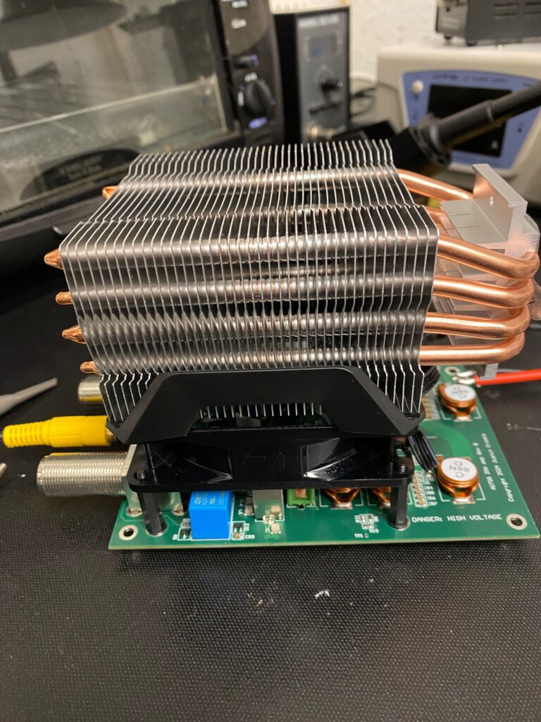
The surface mount parts are on! I still need to do all the through hole parts, and then test the darn thing… more updates later today.
Update 1: Through hole parts are on, mechanicals look good. Need to add heat pipes from the FETs still, but the fan is nice and quiet (which was the goal).
So far two errors, one fixed. First, I inverted a signal I shouldn’t have, so had to flip it. Fortunately I had the right part on hand. Fixed! Second, I need the power supply to be responsive, but it looks like I over-tweaked the control loop and the variable output voltage isn’t always stable. I have a test jumper which forces it to 1.5 volts output, so no FETs were harmed! I’ll make some modifications and let you know how it worked.

Update 2: I didn’t simulate the power supply control circuit, and used rules of thumb. Bad idea. It was not stable. Fortunately I had the jumper in place that doesn’t let the output exceed 2 volts, so nothing damaged. Fully simulated, with op amp for feedback now. My eyes aren’t what they used to be, but I managed to get the new R and C for the control loop populated. Maybe tomorrow after work I’ll have time to bend the heat pipes!
Here is the power circuit if anyone is curious. V3 is the output from the envelope tracking circuit.
Update 3: Definitely won’t be transmitting 1000 watts tonight. I was transmitting Morse code into a dummy load at about 10 watts in, 300 watts out, and everything looked good. The load was heating up, amplifier was running cool, waveforms looked good on my test points. Then I tried SSB. About 10 seconds in my power supply flat-lined. Looks like I have some troubleshooting to do.
Update 4: I went to troubleshoot my amplifier, thinking it was a blown FET. Powered it up at a low voltage, and it was working just fine! Left the cooling system off and ramped up power, probing various points and checking temperature as I went. As soon as I got to about 100 watts, I noticed it would work fine… for about a second. Then its power would drop a lot.
I re-checked the design and realized I was supposed to remove the ferrite cores in my tunable inductors. I designed them for air core alone. I took out 2 of the three cores, but the third was melted in place.
It’ll be a pain to replace, but at least now I know what the problem is!
Update 5:

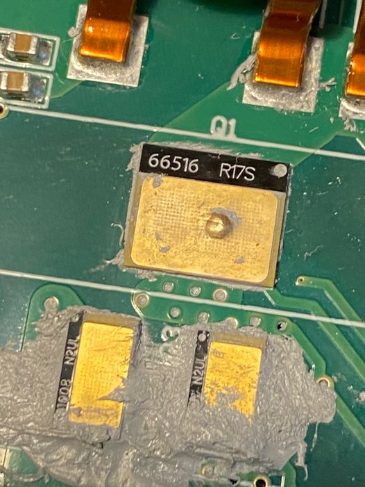
It actually was a blown FET. I had one backup. Replaced it and took some measurements with the heatsink off, in 2 second bursts.
With my IC-7300 set to 3% output (not enough to properly square up the gate drive signal), without the heat sink, I was measuring a power draw of 62 watts, and an RF output post-filter of only 34 watts. I have some concerns that I am not achieving the efficiency I was looking for. I’m thinking when the replacement FET arrives, I’ll re-bias it for less gain (12 dB?) and shoot for 400W instead of 1 kW.

Leave a Reply