For most of my career, the goal has been isolating from magnetic fields coupling where they shouldn’t, so building something to intentionally radiate was a refreshing change of pace.
Design
I already had some 4 inch aluminum tape and 1 inch copper tape. My first thought was to cover some PVC pipes, but I didn’t have them and didn’t feel like going into town. I also wasn’t sure what I’d do for a tuning capacitor.
I’ve always thought corrugated plastic (your typical yard sign) had some potential so I decided to see how it worked structurally for a magnetic transmitting loop. As a bonus, 4 millimeters of corrugated polyethylene would make a great high voltage capacitor!
I ordered my yard signs and did some research and calculations. I wanted as much bandwidth as possible on 20 meters. I had been disappointed in the performance of my attic full-wave loop on 20m, and hoped that the mag loop on my balcony would perform better (spoiler: it did).
I didn’t really care about sharp nulls, so I settled on a single loop with circumference / perimeter of about 1/3 λ, probably in the shape of a square. Wikipedia had the equation for how much radiation resistance I could expect, which worked out to about 1.6 ohms.
https://en.wikipedia.org/wiki/Loop_antenna
I saved myself the effort of estimating how much inductance I’d have and just used this calculator:
https://www.allaboutcircuits.com/tools/rectangle-loop-inductance-calculator/
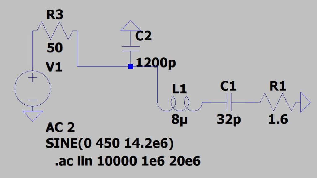
Then using F=1/(2π sqrt(LC)) I had a good starting point for my tuning capacitance. I would build a square, a little over 5 feet on a side, in two sections, with 4 inch aluminum tape on the outside. The sections would overlap at the top by a couple of inches for my tuning capacitance, and at the bottom I would use a shunt capacitor to match to 50 ohms (plus some reactance, but who cares? We already need a tuning cap at the top!).
I used this tool:
to determine that I’d need a little over 1200 pF for my shunt capacitor. I threw it all in LT Spice to see if it looked reasonable. It looked good enough to proceed to building it!

From the model, it was clear that the tuning capacitor C1 would see some pretty high voltages, but the matching capacitor, C2, would not.
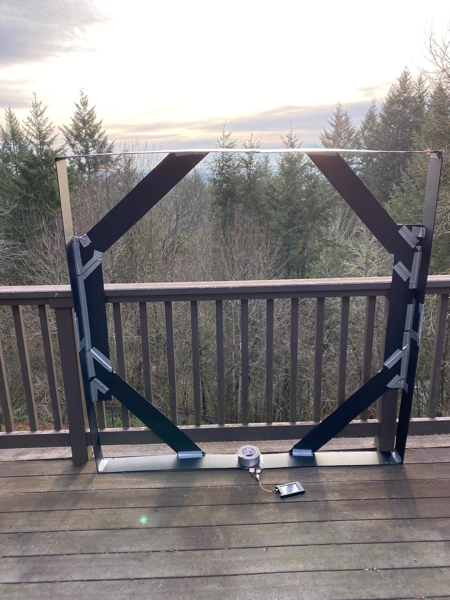
I cut some strips of yard sign material with my Dremel Ultra saw (I’m not really a power tool guy, but that was perfect for the job), duct taped together the two sides of the square, and added the 4 inch aluminum tape to the outside, leaving 1/4″ margin at the ends so the tuning capacitor couldn’t arc through the air alone (it’d have to go through 4 mm corrugated plastic). It looked like my tuning capacitor would need about 3-4″ of overlap from the calculations, but in practice it turned out to be a fair bit less than that.
For the 1200 pF cap, I used some 8 mil x 4 inch mat tape I had left over from my Jiu Jitsu days, with 4″ aluminum tape on both sides (avoiding the edges), taped to corrugated plastic for structure. Update: I guess mat tape is PVC, which will HEAT UP when exposed to RF, so probably not a good choice… Something store-bought might have worked just as well or better, but I didn’t have anything on hand. The online capacitor calculator predicted about 60 pF per square inch, which turned out to be pretty close. I added 1 inch strips of copper tape (easier to solder to, and the thin oxide layer on the aluminum tape formed a capacitor with the copper too large to affect anything), and put it all together.
I tried tuning it in my garage, but something was way off. So I took it up to my balcony and tried there. Much better! Everything but the tuning capacitor almost exactly matched expectations. Surprisingly, my IC-7300 antenna tuner was able to match it across about 200 kHz of bandwidth!
With the mag loop, my noise floor was more than a full S unit lower (roughly 6 dB) than the attic antenna, and the signals were coming in strong. So I had to try transmitting. After a couple of easy contacts, one on each coast of the U.S., I decided the project was a success.
And all for about $50 in parts. My wife saw it and said, “Oh, you built a portal!” And in a number of ways, it really is!
Note: If I could do it again, I would probably use the PVC pipes. The corrugated plastic is not that great in the wind…
Next Steps
I actually built two of the rectangles. I’m thinking about putting the two together as a 2-turn loop, with a larger capacitor of course, and tuning for 80 meters. I still have zero contacts logged on 80 meters.

Leave a Reply